RESISTANCE TEMPERATURE DETECTORS – RTDs
OVERVIEW
Resistance Temperature Detectors, also known as RTD’s, are wire wound and thin film devices which incorporate pure metals or certain alloys that increase in resistance as temperature increases and, conversely, decrease in resistance as temperature decreases. RTDs are similar to thermocouples in that they convert changes in temperature to voltage signals by the measurement of resistance. As a RTD gets hotter the resistance measured on it’s element becomes larger, as it cools the resistance becomes smaller.
THE PLATINUM ELEMENT RTD
The most commonly used type of RTD element is Platinum, these models are often referred to as PRTs or PRT100s. Platinum elements are popular because they can be used over a wide range of temperatures and feature a quick response time. Platinum’s coefficient of resistance is nearly linear, as such, by using a platinum element resolutions of ±0.1 °C or better are possible.
OTHER ELEMENTS
Other elements can be used in RTD’s which are less costly, the most commonly used alternatives are Copper and Nickel. The advantage to this is that the RTD will cost less money to manufacture and have a lower replacement value, but the drawback is that these elements have more restriction on the ranges they can be used due to non-linearities in the resistance vs. voltage curve. Also, there are problems with wire oxidation problems which are known to occur when copper is used as the element.
WHY CHOOSE AN RTD?
The advantages of RTD’s include: stable output for long period of time, ease of recalibration, and accurate readings over relatively narrow temperature spans. When compared to thermocouples their disadvantages are: higher sensitivity to vibration, smaller overall temperature range, and a greater initial cost. For more help in determining if an RTD is the correct choice for your application, please consult our knowledgeable sales staff.
PROLONGING LIFE AND ELIMINATING MEASUREMENT ERRORS
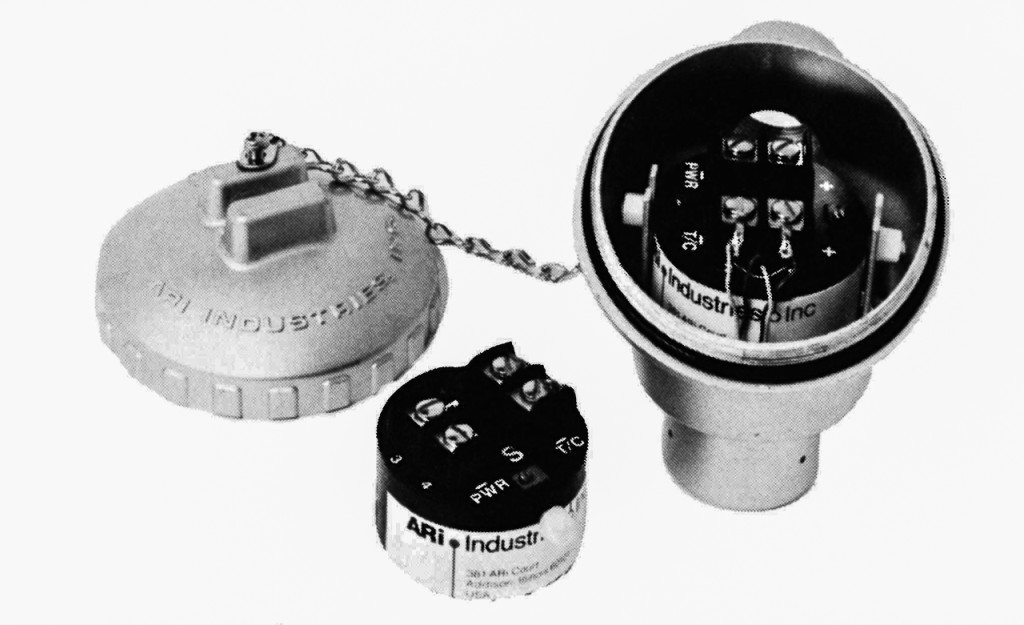
To get the maximum life from your Resistance Temperature Detector it is recommended that you use a protective well and terminal head. The well serves to protect the RTD from damage by the gas or liquid being measured. Protecting wells are available in stainless steel, carbon steel, Inconel, or cast iron, and they are used for temperatures up to 1100°C. To eliminate errors in taking measurements it is necessary to compensate for the length of leadwire used to connect the RTD to the readout. The calculations to correct this are relatively simple, and there are also 3-wire and 4-wire designs which help to minimize such errors. An example of a typical 3-wire measuring circuit is shown in the RTD Specifications Section.
Features of ARiDET Mineral Insulated Resistance Temperature Detectors
◦Time Constant of 2.2 sec or less
◦Temperature Range: -200 to +600 °C
◦Pressure Range: Vacuum to +50,000 PSIa
◦Shock Resistance to 1000G in all 3 axis
◦Withstand Vibration of ±50G, 60 to 2000HZ
◦Accuracy:±1 ohm @ 0 °C (±0.1% for 100 ohm)
◦Reproductibility: ±0.1% of resistance for 100 ohm element
◦Very Long Lengths. Entire length can be exposed to high temperature
◦Available with 4-20ma temperature transmitter/amplifier
◦Superior corrosion resistance with low carbon 316 ST/ST sheaths
◦Can be sharply bent with no change in performance
◦Full Technical Specifications
LABRATORY ACCURACY WITH INDUSTRIAL RUGGEDNESS
Platinum resistance temperature detectors are used for interpolation between the IPTS-68 fixed temperature points of ice and antimony (0°C to 630.74°C), generally used where accuracy and stability are most important. The ARiDET® approach to RTD’s will bring ±.05° laboratory accuracy to the toughest industrial processes – without special handling considerations. ARi Industries Inc. has combined the inherent accuracy of a precisely wound Platinum resistance element with AeroPak® compacted ceramic insulated cable. The result is a low cost yet rugged sensor that will take factory handling – retaining the stability needed for today’s precise process control.
Available with either the 99.999%+ high purity JIS C-1604-81 or 99.99% DIN 43760 temperature vs. resistance curve.
See the temperature vs. resistance tables in the RTD charts section for how to obtain laboratory accuracy.
For a more detailed explanation of how resistance temperature detectors work please visit our technical specifications page.
SPECIFICATIONS
SELECTION / MATCHING
Completed probes may be matched in pairs to the nearest 0.01 ohm at 0 °C for differential temperature measurements to 0.05 °C
Completed probes may be supplied with selected ice point resistances within a narrow band to eliminate the need for compensation in indicating circuits.
ARi ARiDET® consists of a specially installed platinum resistance element completely encased in compacted metallic oxide insulation of high thermoconductivity to insure minimum temperature differential between the sensor surface and the element. Standard sensors have 3 constantan equi-resistance lead wires in the lead portion with compacted MgO insulation. Sheath material is 316 L ST/ST in fully annealed condition. Performance specifications are shown for the element portion and the lead portion.

RTD |
||||
|---|---|---|---|---|
| LEAD | ELEMENT | |||
| Accuracy | — | ± 0.01 Ω at 0 °C | ||
| Stability* | — | -130 to 93 °C ± 0.05% | -130 to 315 °C ± 0.10% | 315 to 600 °C ± 0.50% |
| Temp Range | -250 to 1000 °C | -200 to 600 °C | ||
| Measuring Current | — | 10 milliamps DC max | ||
| Vibration Shock | Vibration: ± 50G, 60 to 2000 Hz | |||
| Shock: 1000G | ||||
| Along all three mutually perpendicular axes when correctly mounted. | ||||
| Temp/Res. Curve | — | 0.00385 Ω / Ω / °C per DIN 43760 | 0.003916 Ω / Ω / °C per JIS C 1604-81 | |
| Individual Calib. | — | To nearest ± 0.01 Ω at °C | ||
| Self Heating Error | — | Less than 0.02 °C/MW | ||
| Max External Pressure | 50,000 psi (3510 Kg/cm²) | |||
| Stock Length L | 24 inches (610 mm) | |||
*Maximum ice point shift after long term thermal cycling.
SENSOR PARAMETERS |
||||||
|---|---|---|---|---|---|---|
| 1/8″ | 3/16″ | 1/4″ | ||||
| inch | mm | inch | mm | inch | mm | |
| Diameter | 0.125 | 3.18 | 0.188 | 4.78 | 0.250 | 6.35 |
| Temp. Sensitive Length | 1.1 | 28.0 | 1.1 | 28.0 | 1.1 | 28.0 |
| Bending Restriction, Distance from tip to be left straight | 2.1 | 53.3 | 2.1 | 53.3 | 2.1 | 53.3 |
| Minimum Bending Radius | 0.5 | 12.7 | 0.75 | 19.0 | 1.0 | 25.4 |
| Maximum Length | 700 ft | 213 m | 300 ft | 91 m | 175 ft | 53 m |
| Minimum Length | 4 | 102 | 4 | 102 | 4 | 102 |
| Constantan 3-Wire Leads, Resistance in Ω/in each wire | 0.061 | 0.025 | 0.015 | |||
TYPICAL 3-WIRE MEASURING CIRCUIT FOR RTD’S
A 3-wire system may be used to eliminate the effect of lead wire resistance changes by introducing RL (lead wire resistance) into each leg of the bridge. The third lead wire is added to the detector circuit without effecting bridge balance. The resultant circuit is sensitive only to resistance element temperature changes.

TIME RESPONSE CHARATERISTICS
The response of an ARi Resistance Temperature Detector is defined by 2 noticable characteristics when exposed to an instantaneous (step) change in enviroment temperature. These are:
A.) Time Constant (tau). The time to reach 63.2% of the complete step change in temperature.
B.) Response Time. Time to reach within 0.5% of the final temperature in a step change.
This is approximately equal to 5 times the time constant
The response of a temperature sensor to a step change in environment temperature tends to follow a second order differential equation. However, this is approximate, since if the mass of the sensor is small in relation to the mass of the fluid passing over it (such as in the case of a liquid), the response may approach a first order differential equation. A typical response is as follows:

Time constant has application for more common experiences in process control, ie, ramp change or sinusoidal changes in enviromental temperature. The response of a sensor under these conditions are:

Time constant is related to the environmental conditions by the following approximate relation (Ref NASA TN 2599)

Knowing the time constant for a given sensor at one given set of conditions, it can be computed for another set of conditions.
MODEL’S AND DESCRIPTIONS


Calibration:
All assemblies shown can be supplied with a different calibration and 0°C resistance value.
Calibration |
|
|---|---|
| Calibration Ω / Ω / °C | ARi Symbol |
| 0.00385 | 100 DIN |
| 0.003916 | 100 |
Lengths:
Standard lengths for the 3 diameters is 24″ (610mm). Longer lengths of compacted MgO insulated lead portion can be supplied up to the following.
Standard Sheath Diameters |
||||
|---|---|---|---|---|
| Diameter | Maximum Length | |||
| (inch) | (mm) | (feet) | (meters) | |
| 0.125 | 3.18 | 700 | 213 | |
| 0.188 | 4.78 | 300 | 91 | |
| 0.250 | 6.35 | 175 | 53 | |
Duplex elements at 0.250″ diameter will be approximately the same length.
Duplex Elements:
Can be supplied at 0.250″ diameter only where suitable terminations can be made. Temperature transmitters for duplex circuits are not available for internal mounting in connection heads. The following styles can be made with duplex elements. Specify the 6 wire style for duplex elements.
Styles / Duplex Elements |
|||||
|---|---|---|---|---|---|
| Number Of Wire | Bare Wire | Extension Wire | Standard Size Connection Head | Hinged Cover Connection Head | Nylon Connection Head |
| 3-Wire Style | PRT-14.3 | PRT-22.3 | PRT-96.3 | PRT-296.3 | PRT-396.3 |
| 6-Wire Style | PRT-14.6 | PRT-22.6 | PRT-96.6 | PRT-296.6 | PRT-396.6 |
Single Circuit 4 Wire:
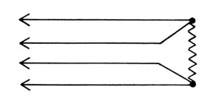
PRT Type assemblies can be made with four (4) leadwires with the following circuit.

*Send us your drawings/sketches for prompt quotations.
How To Order:
- Establish Part Number:

- Specify quantity and any special tests.
- Specify installation accessories and quantity.
- If temperature is required to produce 4-20ma with 28VDC excitation, use Style PRTX.
ACCESSORIES
Pressure or Vacuum Tight Applications

Compression Fittings
300 series stainless steel with 1/8″ NPT thread for setting immersion and pressure tight entry into vessels, process lines, etc. Useable to 4000 psi differential pressure.
| Diameter (inch) | 0.125 | 0.188 | 0.250 |
| Part Number | PTM-D2SS | PTM-E2SS | PTM-F2SS |
Surface or Pipe Measurements

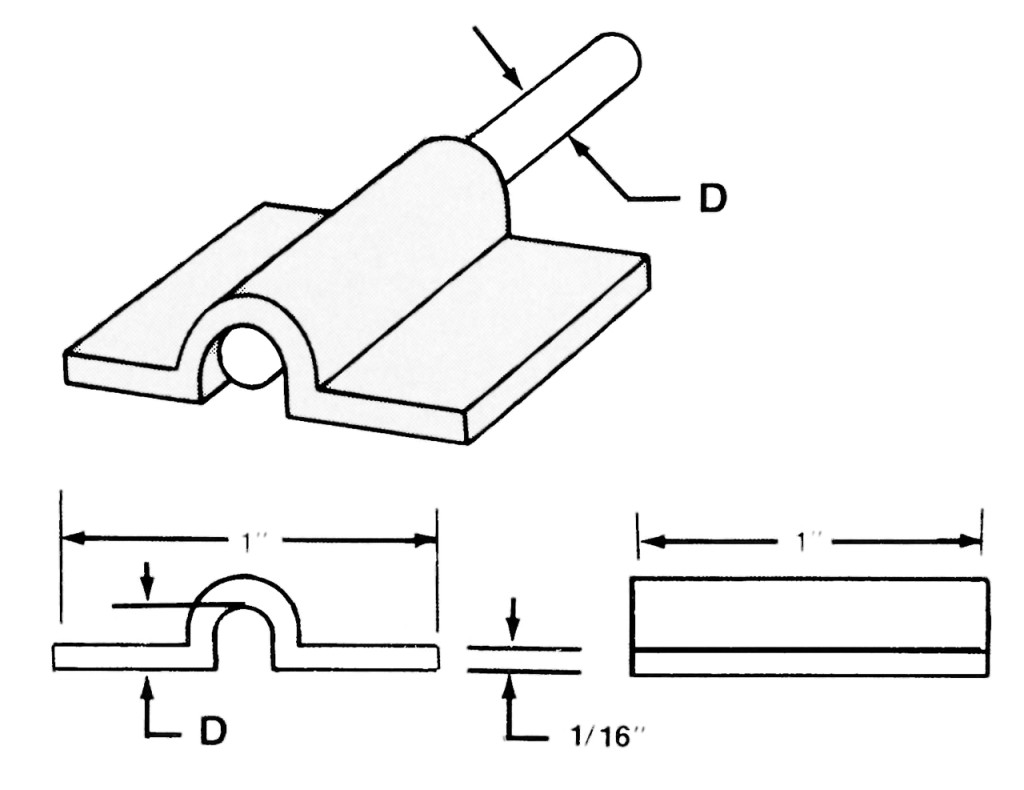
300 series ST/ST clamp that can be welded, brazed, spot welded, or glued to the surface of the item being measured. The wide tabs insure adequate heat flow between the sensor and measured object to keep conduction errors at a minimum.
| Diameter (inch) | 0.125 | 0.188 | 0.250 |
| Part Number | 490999-D | 490999-E | 490999-F |
3-Conductor Lead Wire
Part No. 012529 – 3-Conductor stranded nickel 20 ga. teflon over each with tinned copper braid overall and teflon wrap overall. Color coded, 2 black, 1 red.
Temperature Transmitters (Spring Loaded)

Part No. 47041 (fits T-96.3, T-296.3, T-396.3) – Specify calibration and span
Please contact us for further information or any special requirements you may have.
We want to hear from you:
800-237-6725 (Toll Free)
630-953-9100 (Phone)
630-953-0590 (Fax)


